“## Surge protection
When to use surge protection#
We recommend surge protection devices (SPDs) for the RS-485 bus in these cases:
- The bus is run outdoors
- The bus passes through areas outside the lightning protection system’s protection zone
How it works#
Surge protection, unlike a bus isolator, channels the induced voltage to the PEN/PE terminal, thereby protecting the input circuitry of your devices.
Power supply protection#
Power supply in a protected area#
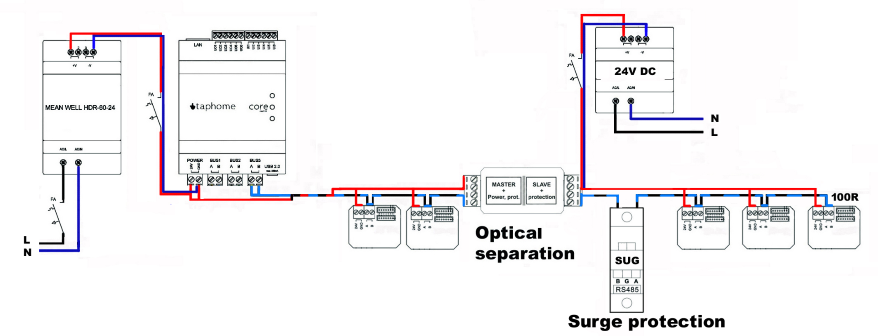
When using the circuit shown in the attached diagram, there is no need to protect the positive pole of the power supply if the supply is located in a protected area.
Power supply in an unprotected area#
If the supply is located in an unprotected area, you need to use:
- Surge protection for the 24 V DC distribution
- Type C surge protection on the AC supply side
The actual design of the surge path depends on the cross-section of the incoming low-voltage distribution cable and the possibility of grounding the system.
Circuit diagram#
In the attached diagram, surge protection is used only on the supply line to the remote section located outdoors.
Warning: This is only a partial solution for protecting the bus. For full protection, see the section below.
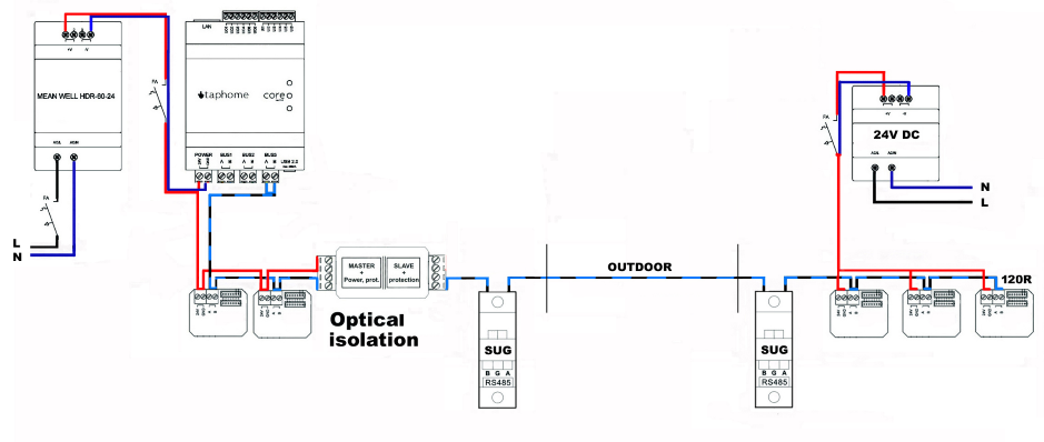
Complete bus protection#
A complete protection solution requires two surge protection devices in the following cases:
When full protection is required#
The bus passes through sections that:
- Are, and then are not, within the protection zone of lightning protection systems
- Do not have the ability to absorb the energy field created by atmospheric discharges
Protection placements#
Surge protection devices are installed at the entry points of the conductors into protected zones.
Important: This applies regardless of whether an optical isolator is used on the bus.
Modbus bus protection#
When to use#
For a Modbus bus run outdoors outside the lightning protection system’s protection zone, we recommend using surge protection.
Power supply protection#
When using the circuit shown in the attached diagram, the positive pole of the power supply does not require protection, as it is not used.
Standards requirements#
When designing the system correctly, the risk of electromagnetic impulses from atmospheric discharges must not be neglected, in accordance with the STN EN 62 305 standards.
Circuit diagram#
The attached diagram shows complete protection of the Modbus bus line, equipped with surge protection on both sides of the bus conductors.

Surge protection for temperature measurement#
Measurement with resistance sensors (Pt100)#
When measuring temperature using resistance sensors (e.g., Pt100), consider:
- The ohmic resistance of the extension cables
- The damping resistors of protective devices
Effect on measurement accuracy#
Pay attention to measurement accuracy!
In a two-wire measurement, the SPD resistance can distort the measured result.
Example error:
- Sum of damping resistors: 4 Ω
- Measurement error at 0 °C: 4% (104 Ω instead of 100 Ω)
Solution#
Two-stage protective circuits are available in a version without damping resistors to minimize the SPD’s impact on measurement accuracy.
Surge protection for current loops#
4–20 mA signal#
Measured values are transmitted using the standardized 4–20 mA signal, which is used mainly for applications with longer conductors.
Advantages of current transmission#
- The cable’s resistance does not affect the current conveying the measured value
- Two signal wires are used
- No additional reference potential is required
- They are carried in an isolated state from earth potential
Protection#
Protection is required at both ends!
To protect this type of application from surges, SPDs are required at both ends of the conductors.
SPD construction#
The relevant SPD is equipped with a multi-stage protection circuit, which provides protection against:
- Transient voltage in normal operation between signal conductors
- Common-mode voltage to earth at both ends”